


The expected life of linear bearings containing rolling elements used so extensively in machine designs (like that for rotary bearings, ballscrews, and other components) is often expressed as an L10 (life-10%) value. For linear bearings based on rolling (not sliding) contact between subcomponents, this theoretical L10 value is defined by International Organization for Standardization publication ISO 14728-1 as:

Where L10 is how long 90% of all linear bearings put into the defined service will deliver.
C = The system’s dynamic load capacity.
P = The application’s applied load.
The 10/3 expression is used for linear bearings containing cylindrical rollers to bear the load; the cubed expression is used for linear bearings containing balls to bear the load.
One note of caution: Dynamic load capacities can be defined with 50 km or 100 km as the reference distance. Which reference distance is used depends on the manufacturer and (in some cases) even the specific product. So before making any calculations, design engineers should review manufacturer catalog pages relating to the exact product being specified to select the correct service-life equation. There is an ISO-defined dynamic-load rating conversion formula to switch between the two expressions, and some manufacturers do designate C50 and C100 to help avoid confusion.
Another note of caution: Achieving anything near the unadjusted L10 projected life is usually impossible as linear bearings in real-world applications are subject to complex load distributions, contamination, variable temperatures, and chemicals as well as compromising mounting and lubrication routines.

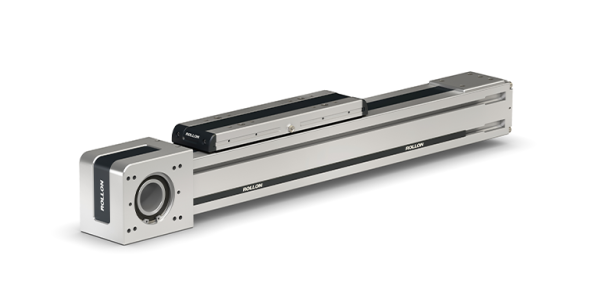
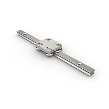
Shown here is an exploded view of the Rollon R-Smart 160 linear actuator built to deliver long life even when tasked with transporting heavy payloads in various orientations and demanding work cycles. R-SMART-series actuators feature extruded and anodized aluminum self-supporting frames from 120 to 220 mm and dual rails traversed by four or more recirculating-ball-bearing blocks.
Of course, not all power-transmission components used in motion designs contain rolling elements so L10 expressions aren’t universally applicable. Though beyond the scope of this article, it’s worth noting that the life of sliding-element mechanical components such as linear round-rail slides and dovetail slides is a function of pressure and velocity (PV) and other application values that are partially outlined by ISO technical committee (TC) 123.
Years of service — another way to express life:
Sometimes more intuitive than L10 values are expressions of linear-design service life expressed in months or years. Converting between time-based expressions and L10 expressions (to confirm a selected actuator is suitable, for example) requires use of the application’s on-off or duty cycle. This duty cycle depends on the durations of required travel including active move and reversal periods to execute full and partial strokes, any dwells per hour, and daily hours operated — as in one, two, or three shifts per day, for example — minus any time allotted for operational holidays and maintenance or tool changeovers.

Many OEMs begin machine builds having a notion of the design’s required years of service. Rollon applications engineers can help correlate that value to a life value expressed as an axis’ payload-bearing carriage distance traveled before failure.
Assume we’re specifying a linear actuator containing a motor-driven belt drive that must jog a non-cantilevered 2-kg payload back and forth over a 500-mm axis within a 2-sec cycle time punctuated by 1-sec pauses. Also assume the supplier has pre-integrated a motor, rotary bearing, coupling, belt drive, and sealing system capable of satisfying all target applications’ requirements. If our actuator runs 16 hours a day 365 days a year and must perform without failure for one decade, it must make 70,080,000 cycles and travel some 70,080 km. As generated by the design configurator at my.rollon.com, possible solutions for this design include a:
- Rollon E-SMART 30 SP2 linear actuator with a life exceeding 350,000 km.
- Rollon Speedy SAB 120 CX linear actuator with a life of 80,000 km.
- Rollon R-SMART 120 SP4 linear actuator with a life exceeding 350,000 km.
The expression of life in cycles or distance per year allows verification of how many years a given actuator can reliably deliver high-performance motion.
Life calculations that account for all conditions
Now consider life equations that account for real-world conditions affecting the duration of a given linear system’s service. Rollon publishes a straightforward but more thorough life calculation that augments standard L10 calculations to let design engineers account for their application’s unique conditions and requirements.
Check out this video for one specific example of how actuator life is computed with Rollon’s method of calculation.
More specifically, Rollon life equations include the dynamic load rating Fdyn of the chosen actuator in the working axis direction, an equivalent acting load Peq that accounts for loads and moments in all directions, and a service factor fi to adjust for the level of shock and vibration an actuator will need to withstand. So, for an assembly containing ball-bearing linear-guide elements:

Dynamic load capacity Fdyn values are tested, verified, and published by the linear-component manufacturer to indicate the constant-magnitude load normal to load-bearing elements that the component can withstand while still delivering the expected lifetime travel sans fatigue-induced flaking and other forms of mechanical degradation.
The service factor fi on the other hand accounts for shock loading and sudden reversals to which the actuator may be subject. This sometimes-unpredictable value is included in safety values as a ratings ratio of the baseline slow-moving or static load to the maximum combined static load (including shock). Anything beyond these values will cause plastic rolling-element and raceway deformation of 0.01% or more of the rolling-element diameter. Rollon recommends use of fi = 1.5 to 2 for slow-moving (<1 m/sec) and slow-reversing applications in clean settings without shocks and vibrations. Rollon recommends use of fi = 2 to 3 for moderate-speed (1 to 2 m/sec) and moderately-quick reversing applications involving slight vibrations. Rollon recommends use of fi of more than a value of 3 for high-speed (>2 m/sec) applications involving exposure to contamination, short strokes, shock and vibrations, and quick (α > 10 m/sec2) directional changes.
Connect with Rollon for realistic life projections:
For more information on linear motion components that can deliver long service life, visit rollon.com. Or to analyze ways to satisfy your own application’s required life, connect with a team of applications engineers, and explore the extensive capabilities of Rollon’s linear and multi-axis cartesian offerings, visit the myRollon online configurator.